exoplan Tutorial: Implant Planning from DICOM to Surgical Guide
exoplan is the guided surgery module within the exocad ecosystem, where the entire implant planning workflow takes place: from loading DICOM data to exporting a surgical guide for 3D printing. This exoplan tutorial walks through each step of a real protocol — the way it is done in a clinic or a lab. We will cover CBCT import, STL scan alignment, implant positioning, CAD library selection and outputting a finished guide as STL.
The DentalLibs catalog holds over 1200 libraries for exoplan (1271 at the moment), so finding a component for a specific implant system is usually not a problem — but more on that below, once we reach positioning.
DICOM import: where implant planning in exoplan begins
Planning relies on CBCT data. exoplan accepts a series of slices in DICOM format — typically a folder of .dcm files exported from the scanner. On import, the software builds a volumetric reconstruction from the slices, which you then rotate, crop out the excess field of view and bring into an anatomically correct orientation.
Once the volume is built, it makes sense to set the basic references right away so you do not have to redo them later.
- Set the occlusal plane and the axis of symmetry — the implant angulation is calculated from them.
- Draw the panoramic curve along the arch for convenient slices.
- Mark the mandibular nerve canal to visualize the safe zone.
- Adjust the density threshold if bone separates poorly from soft tissue.
Aligning STL scans to CBCT (matching)
CBCT shows bone well but does not provide an accurate surface of the teeth and gingiva — that comes from an intraoral scan or a scanned plaster model in STL format. In exoplan these data are overlaid onto the DICOM using shared references: you mark a few matching points on the crowns and the software performs a precise best-fit alignment.
Good alignment is critical: the base of the surgical guide will later seat on that STL surface. If the scan drifts relative to the bone, the guide will sit with a gap and all the planning accuracy is lost at the printing stage.
In edentulous areas there is nothing to match against — in that case radiopaque markers or a dual scan with a temporary prosthesis are used.
Implant positioning and CAD library selection
Once the volume and scans are aligned, you move on to the actual implant planning: the implant is placed in the bone with regard to density, cortical thickness and the future prosthetic crown (prosthetically driven planning). The axis is set so the screw channel emerges at the correct point — this determines the choice between screw-retained and cement-retained fixation.
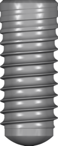
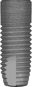
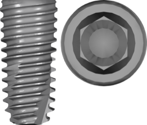
Next you pick a CAD library for the specific system: brand, platform (NP/RP/WP), diameter and length. The library carries the exact geometry of the implant and the compatible prosthetic component — for example, a titanium base (Ti-Base) for the future crown. A mistake at this step carries over into the real surgery, so the platform and diameter are checked against the implant packaging.
If you work in an alternative guided surgery environment — RealGUIDE — the catalog offers ready-made sets such as the Megagen libraries and the 3Dmedica components, which bring the same principles of implant and abutment selection into its interface.
Surgical guide design and sleeve selection
On the planned implants exoplan builds a surgical guide: the base rests on the STL surface, and a guiding sleeve or a key well is placed over each implant. The sleeve is chosen from a library that matches your guided surgery kit — a metal ring, a sleeveless solution or a drill keys system.
The sleeve height and its vertical offset are defined by the drilling protocol of the specific system, so these values are taken from the kit instructions rather than estimated by eye. You also check the support windows, the base wall thickness and the presence of inspection windows to verify seating.
More on matching sleeves to an implant system in a separate article on surgical guides and sleeve libraries in the DentalLibs catalog.
Exporting the guide to STL and 3D printing
The final step of the exoplan tutorial is sending the guide to print. The finished guide is exported to STL and sent to your 3D printer's slicer. It is printed in a biocompatible (Class IIa) photopolymer resin, then post-processed: washing, post-curing and inserting the metal sleeves if they are not printed together with the base.
Before surgery the guide must be tried on a printed model of the jaw or in the mouth — verify that it seats unambiguously, without rocking, and that the inspection windows show a tight fit.
Frequently asked questions about exoplan
Do I need a CBCT for planning in exoplan?
Yes. All 3D planning is built on a volume reconstructed from a DICOM series taken on a scanner. Without a CBCT you cannot plan the implant position in the bone or produce a guided template.
How does exoplan differ from exocad DentalCAD?
exoplan handles guided surgery and the surgical guide, while DentalCAD handles prosthetic design. They work together: the implant is planned in exoplan, and the crown on a Ti-Base is modeled in DentalCAD.
Where can I get a library for my implant system?
The DentalLibs catalog has over 1200 libraries for exoplan — by brand, platform (NP/RP/WP) and diameter. Choose strictly according to the marking on the implant packaging.
In what format is the finished guide exported?
In STL for 3D printing. The file opens in the printer's slicer; it should be printed in a biocompatible resin with subsequent post-processing and sleeve installation.